



Executive Summary
AI did not simply make the rack hotter. It changed what the rack is. For years, a rack was a cabinet full of servers. Today, it can be an integrated AI systemweighing 3,200 to 3,500 pounds. Some larger liquid-cooled accelerated-computing cabinets reach 8,000 pounds. Add direct-to-chip cooling, rear-door heat exchangers, coolant distribution units (CDUs), manifolds, fluid, and the equipment needed to move it all. Physics is back in the meeting.
The AFCOM surveyed average is now 27 kW per rack, up from 7 kW in 2021, nearly 4× in five years across the full data-center mix. AI occupies another tier. A current GB300 NVL72 reaches 142 kW. HPE specifies 132 kW nominal and roughly 192 kW peak design provision
for GB200; next-generation planning ranges reach 227 to 250 kW. A room designed around the average can miss what is coming through the loading dock.
Watts are only the first signal. Teams also need to know what the equipment weighs in operation, where that weight lands, how the rack reaches its position, and how air, coolant, power, and data share the room. Resolve those questions early and the benefits
follow: fewer installation surprises, safer moves, accessible services, and room for the next equipment refresh.
The examples that follow show how room averages can hide local loads, how cooling choices add weight, and how floor and ceiling systems can work together. The goal is practical: build a room that can support the equipment coming in today and adapt when
that equipment changes.
There is no one-size-fits-all floor architecture for AI. For halls expected to change, engineered
raised access flooring is a strong starting point: it combines equipment support with an accessible cooling and service layer, while keeping power and data overhead.
Introduction
For years, one shorthand carried the room: kilowatts per rack. It worked because the physical model moved slowly. Racks were predictable, air dominated, and service routes and weight classes were familiar.
AI changes that equation. The latest platforms arrive with liquid-cooled compute trays, power shelves, high-current busbars, high-speed fabric, and a meaningful aircooled remainder. Facilities need a flexible path for air, direct-to-chip liquid, and hybrid cooling as tenants and platforms change.

The average is rising. AI needs another scale.
Average rack density sets the context. AI platform
requirements drive the design.
Liquid also leaves an air-cooling job to do. NVIDIA uses cold plates for CPUs and GPUs while networking and storage retain an air load. Lenovo describes one current GB300 configuration as approximately 90 percent liquid and 10 percent air; that split is product-specific, not universal. Cooling design now has to account for both heatremoval paths and the equipment, fluid, and maintenance space they require.
That is why the old slab-versus-raised-floor debate needs a reset. Start with what the floor needs to do. A raised access flooring zone can become a dedicated cooling and service layer for airflow, liquid distribution, leak detection, drainage, inspection, and change, while power and data stay coordinated overhead. The floor becomes working infrastructure.
The ceiling is just as active. Busway, cable tray, fiber, containment, lighting, fire protection, and sensors compete for the same volume. Separating underfloor cooling from overhead power and data gives technicians space to inspect, service, and change both.
Section 1: When Density Gains Mass
From a Cabinet of Servers to a Rack-Scale Machine
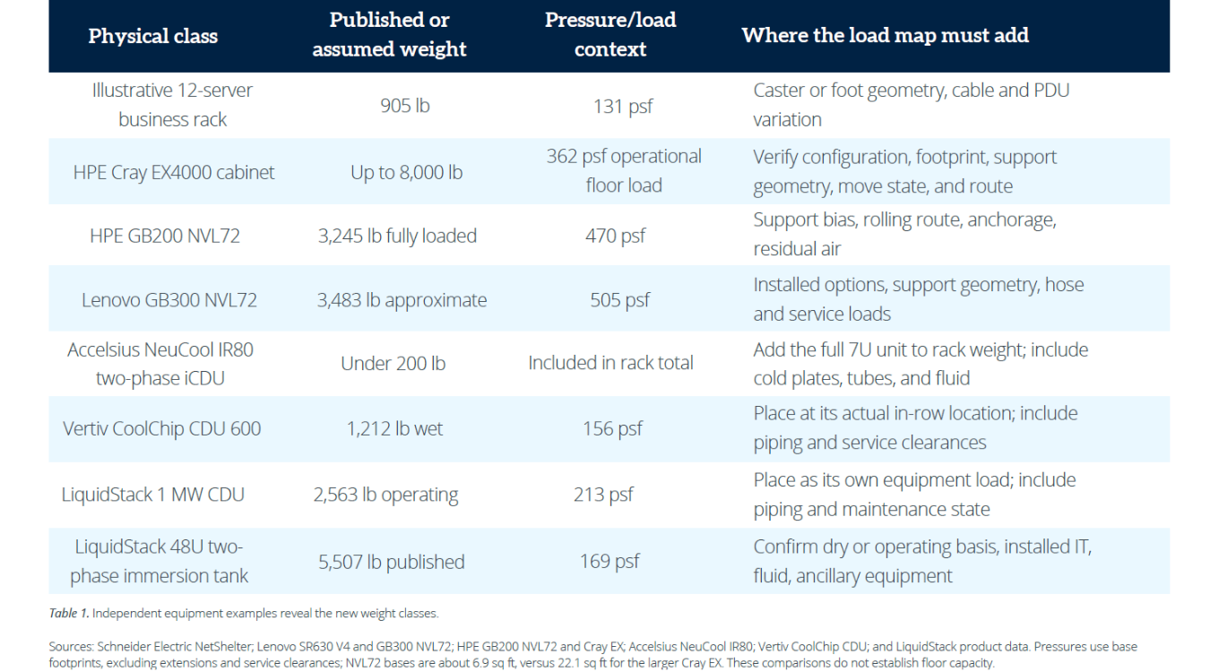
The fastest way to see the shift is to compare physical classes as well
as power ratings. The floor sees mass, geometry, contact points, and movement. Getting those inputs right early helps the team plan installation, daily operation, and eventual replacement.
For the conventional class, assume a 600 by 1,070 millimeter cabinet weighing about 275 pounds, 12 to 20 general-purpose 1U servers at about 40 pounds each, and 150 pounds of switches, PDUs, patching, rails, and cabling. The result is roughly 905 to 1,225 pounds across about 6.9 square feet.
The AI class changes the consequences dramatically. HPE publishes
a fully loaded GB200 NVL72 at 3,245 pounds; Lenovo publishes an approximate 3,483-pound GB300 NVL72. Larger liquidcooled accelerated-computing cabinets can reach 8,000 pounds. Independent CDU examples range from an under-200-pound in-rack unit to wet systems above 1,200 pounds and a 2,563 pound operating unit. An immersion system can exceed 5,500 pounds.
Whatever name is on the cabinet, the building still has to carry it, and the operator still has to move, service, and eventually replace it.
Two things stand out. A current NVL72 rack can weigh roughly 3,200 to 3,500 pounds, while a larger accelerated-computing cabinet can reach 8,000 pounds. But the heaviest system does not necessarily have the highest footprint pressure. Total weight, footprint, and contact geometry tell different parts of the story. Engineers need all three.
Five Questions Behind Every Heavy Rack
Room-average loading helps at the building level, but it says little about what happens under one cabinet. Start with five practical questions, then have the engineering team verify the answers:
1. What does the equipment weigh when fully operating, including coolant and installed accessories?
2. Where does that weight touch the floor: casters, feet, frame rails, panels, or spreaders?
3. What changes while the equipment moves, turns, crosses a seam, or waits in a staging area?
4. How do anchorage, center of gravity, seismic restraint, and the complete panel-to slab load path interact?
5. What credible rack class must this room accept next, and can the change happen without invasive reconstruction?
For structural and mechanical, electrical, and plumbing (MEP) teams, the optional reference below frames the detailed checks:
The practical point: a rack does not spread its weight evenly across the floor. Uneven loading, panel edges, thresholds, and moments when only two casters carry the load can create much higher local forces. An engineered raised access flooring system accounts for those conditions before the rack reaches the room.
Design, ultimate, rolling, and impact ratings answer different questions. A safe final position does not guarantee a safe delivery. Checking the complete raised-floor system and move route protects the schedule, avoids temporary-reinforcement surprises, and preserves a replacement path for the next rack class.
Design Rule
Put each CDU, manifold, pipe, valve, support, and fluid load at its actual location in the load map. Include maintenance conditions and verify how the underfloor cooling system transfers its weight to the slab.
Cooling Technology Creates New Weight Classes
Cooling adds equipment and fluid, and both need support. Raised access flooring can organize those loads while keeping distribution components accessible for inspection and change. With single-phase direct-to-chip cooling, cold plates, manifolds, quick disconnects, and coolant join the rack. Confirm what the published rack weight includes; CDUs, piping, filters, pumps, and facility fluid remain separate loads.
A rear-door heat exchanger adds filled-coil and support weight at the rack rear. Use the selected product's filled weight, credit any removed door, and check the actual support condition. Two-phase systems can reduce liquid volume, not eliminate system weight. If full operating weight is unpublished, the answer is “data required,” not “light.”
Section 2: Rewriting the White-Space Load Path
The 150,000-Square-Foot Paradox
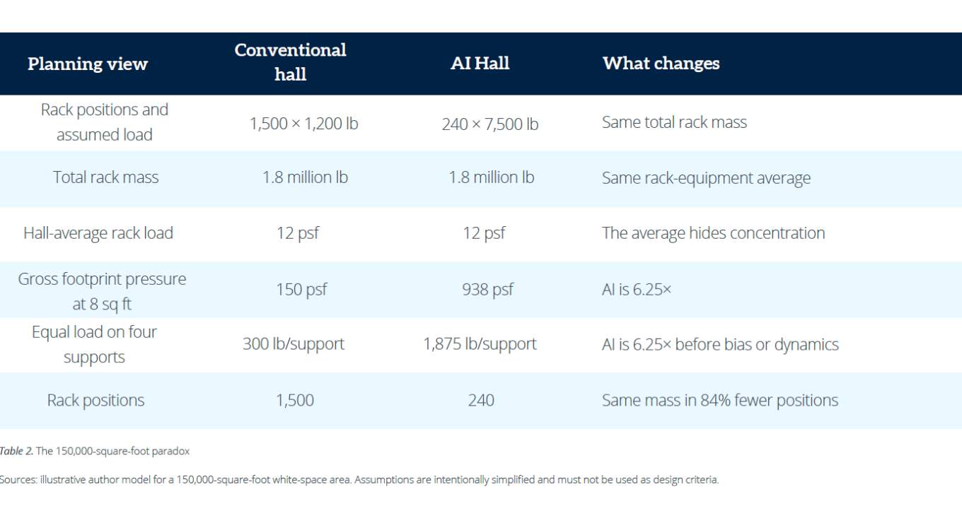
Consider a hypothetical 150,000-square-foot data hall. This simple comparison shows what a room average can miss; it is not a design calculation or a customer result.
Imagine two halls with the same total rack mass:
• Conventional hall: 1,500 racks at 1,200 pounds each.
• AI hall: 240 heavy planning-class racks at 7,500 pounds each.
Both halls contain 1.8 million pounds of rack equipment, averaging 12 pounds per square foot across the entire 150,000 square feet. That excludes floors, cooling, piping, and other facility loads. Stop at the rack-equipment average, and the two halls look structurally identical.
They are not identical. Assuming the same eight-square-foot footprint for each rack, the heavier rack produces 6.25 times the gross footprint pressure and equal-share load on four supports. This is a hypothetical comparison, not the footprint of a specific product. The lesson is straightforward: concentrating weight changes the panel, understructure, slab, anchorage, and move-route checks.
A room average can be mathematically correct and still tell you very little about what happens under the rack.
Design the Journey, Not Only the Destination
Now put that rack on wheels. The load case changes again. Crates, pallet jacks, air skates, lift systems, turns, ramps, panel seams, and thresholds create temporary conditions. A rack that is acceptable at its final position can still exceed the capacity of its delivery path or staging zone.
For access floors, check the complete system in both conditions: equipment at rest and equipment on the move. Table 3 shows why a stationary load rating cannot answer every delivery-route question.
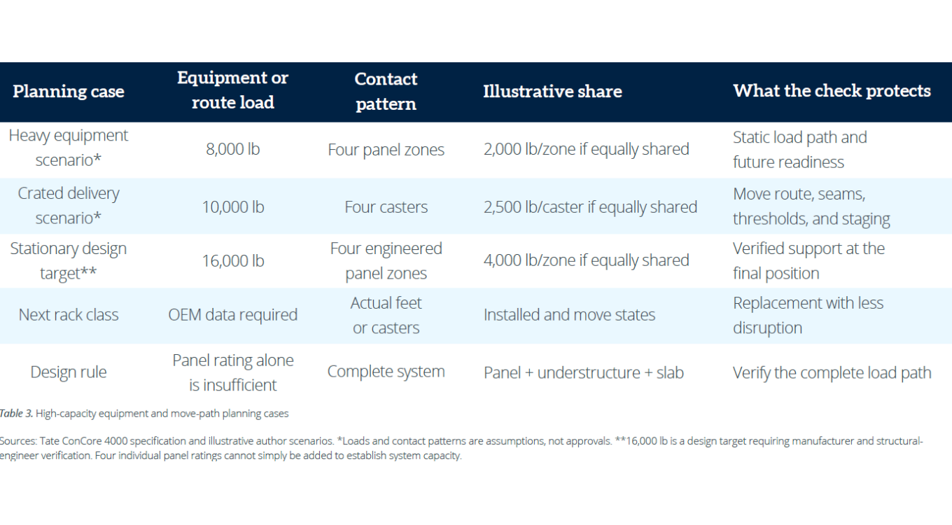
A 16,000-pound stationary load would place 4,000 pounds on each of four panel zones only if shared equally. ConCore 4000 provides a 4,000-pound tested design-load reference. The actual contacts, understructure, slab, and project conditions determine whether the complete arrangement works. The delivery route needs a separate check for caster geometry, seams, turns, and repeated traffic. Specify the floor for the equipment and its journey.
Critical route questions include:
• What is the maximum crated and uncrated move weight?
• How many wheels or supports are engaged during straight movement, turns, and threshold crossings?
• Where do panel edges, ramps, elevator sills, expansion joints, and door transitions occur?
• Which temporary plates, shoring, spreaders, or alternate routes are required?
• Can the replacement path support the next equipment class three to five years from now?
The Advantage of Designing Air and Liquid Together
That remaining air load deserves a real design budget. The split varies by platform and operating condition. At more than 100 kW per rack, even a ten-percent air load needs a deliberate airflow and containment plan.
For many production halls, hybrid cooling is simply how the room works. Cold plates handle the hottest components. Directed air and containment serve the components that remain air cooled. A reardoor heat exchanger may capture part of that air-side heat. Across the room, air-cooled enterprise rows may operate beside liquidcooled AI rows.
Three patterns are already taking shape:
1. Direct-to-chip plus contained air: liquid at the hottest silicon, disciplined air everywhere else.
2. Direct-to-chip plus rear-door heat exchange: liquid at the chip, an RDHx as the air-to-liquid bridge, and containment for the remaining path.
3. Mixed air and liquid halls: different rack classes share the room, but each receives a deliberate cooling and service architecture.
AFCOM respondents are considering several approaches: rear-door exchangers, single- and two-phase direct-to-chip systems, combined direct-to-chip/rear-door designs, and immersion.
Hybrid design makes containment and airflow control more important, not less. Airflow floor panels, hot-aisle or cold-aisle containment, blanking, door performance, and return paths must match the residual heat. Liquid supply and return need separation, leak detection, drainage strategy, access, labeling, isolation, and service zones.
Structural Containment and Airflow
Containment remains an active part of hybrid design because the residual air load still needs a predictable path.

Raised access flooring gives that coordination a practical home. A properly designed underfloor zone can carry airflow and liquid distribution, provide access for inspection, and accommodate leak detection and drainage, while power and data remain overhead. Operators gain a way to service and modify the room without opening the slab or adding every new service to the ceiling.
Water Use Belongs in the Cooling Decision
Site water usage effectiveness, or WUE, is annual on-site water use divided by annual IT energy, usually in liters per kilowatt-hour. Liquid cooling moves heat; it does not guarantee lower water use. Climate, coolant temperature, heat rejection, and controls shape site performance. Electricity generation adds a separate off-site water footprint.
Model both on-site water demand and water used to generate electricity alongside PUE, resilience, maintenance, and community priorities. Compare dry, hybrid, and evaporative heat rejection during concept design. That gives owners a defensible basis for cooling choices and clearer numbers for permitting and community conversations.
Keep the Ceiling From Becoming the Next Bottleneck
Overhead space is not free space. AI rooms add larger power conductors, busway, dense fiber, containment support, sensors, lighting, fire protection, and sometimes coolant distribution. Trapezes and hangers multiply quickly. So do clashes.
A structural ceiling grid can create a regular attachment plane for selected services while containment makes the air boundary repeatable. Verify building connections, seismic bracing, load combinations, attachment capacity, and fire-protection clearances against current project submittals and local code.
Treat floor and ceiling as complementary layers. Plan equipment support, airflow, and horizontal liquid distribution at and below the raised floor. Give busway, cable, containment, and required overhead services room above. Preserve inspection and maintenance access in both.
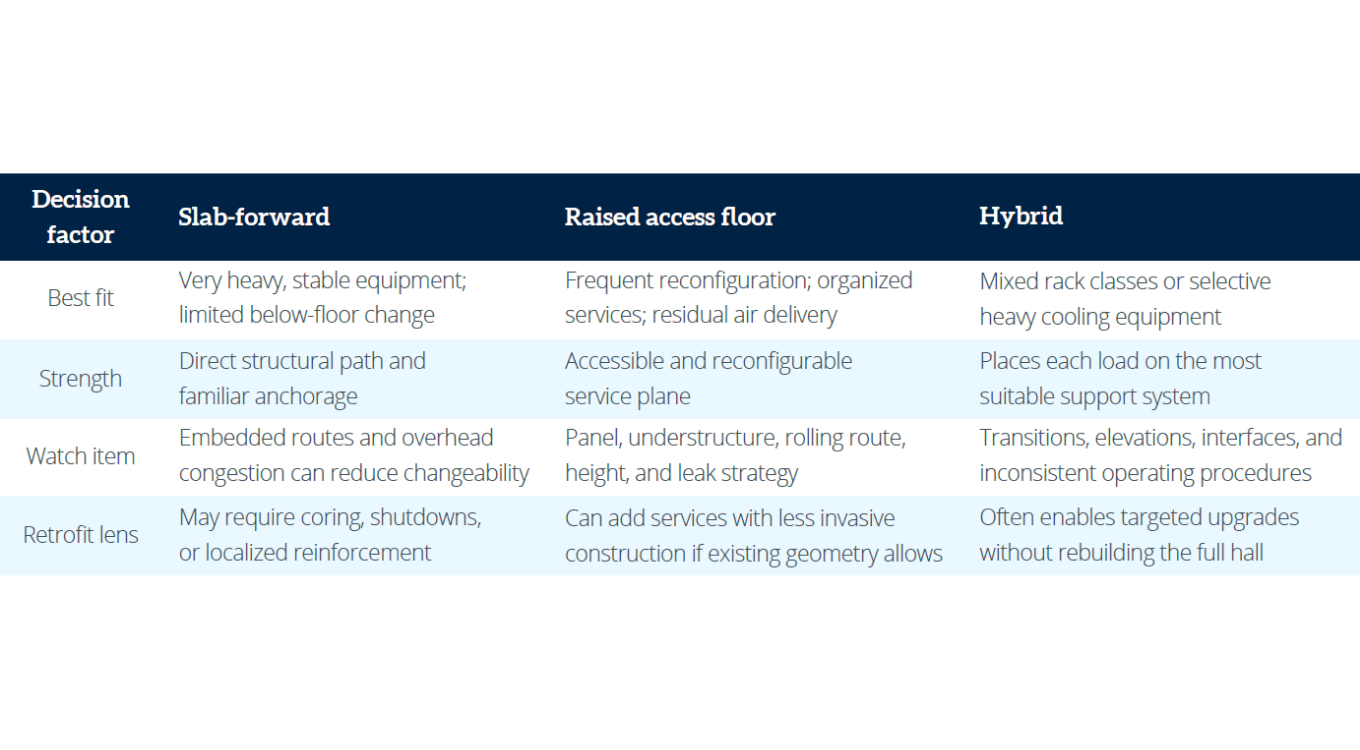
Slab, Raised Floor, or Hybrid?
The right choice depends on the equipment, the building, and how
much change the operator expects.

Bring the Right People in Early
Involve the operator, structural engineer, MEP team, architect, general contractor, rack integrator, cooling vendor, and physical-infrastructure manufacturer before the room geometry is fixed. Interface decisions are cheapest while they are still lines on a drawing.
A slab-on-grade design may be right for extremely heavy, stable equipment with limited need for underfloor change. Raised access flooring may be right when service distribution, residual air, reconfiguration, or retrofit access carries value. A hybrid can put the heaviest skids or immersion systems on slab while using raised access flooring for rack rows and distribution zones.
Retrofit conditions often strengthen the raised access flooring or hybrid case. Existing column grids, slab capacity, floor height, doors, live operations, and shutdown windows constrain the idealized architecture. Selective reinforcement, load-spreading plates, higher capacity panels, dedicated equipment pads, and modular underfloor liquid distribution can add capability without rebuilding the entire hall.
New-build projects offer more freedom to plan for change. Design for a credible range of equipment classes, with room for growth beyond the launch configuration.
Schedule Is a Physical Design Variable
AI schedules leave little room for discovering interface problems in the field. Floor elevations, pipe centers, hose lengths, containment, rack spacing, busway taps, and overhead attachments meet at the same coordinates. One late change can move several trades.
Prefabrication moves coordination, assembly, and testing into a controlled environment. Strong programs define interfaces early, build repeatable modules, inspect welds and assemblies, pressure-test liquid systems, validate flushing or passivation, protect openings for shipment, and recheck after installation.
Precommissioning can include dimensional and visual checks, pressure testing, flushing validation, and project-specific documentation. Agree on that scope early. Factory testing reduces installation risk; site commissioning confirms performance after the system is installed.
Section 3: Bringing the Room Together
Start With What the Room Needs
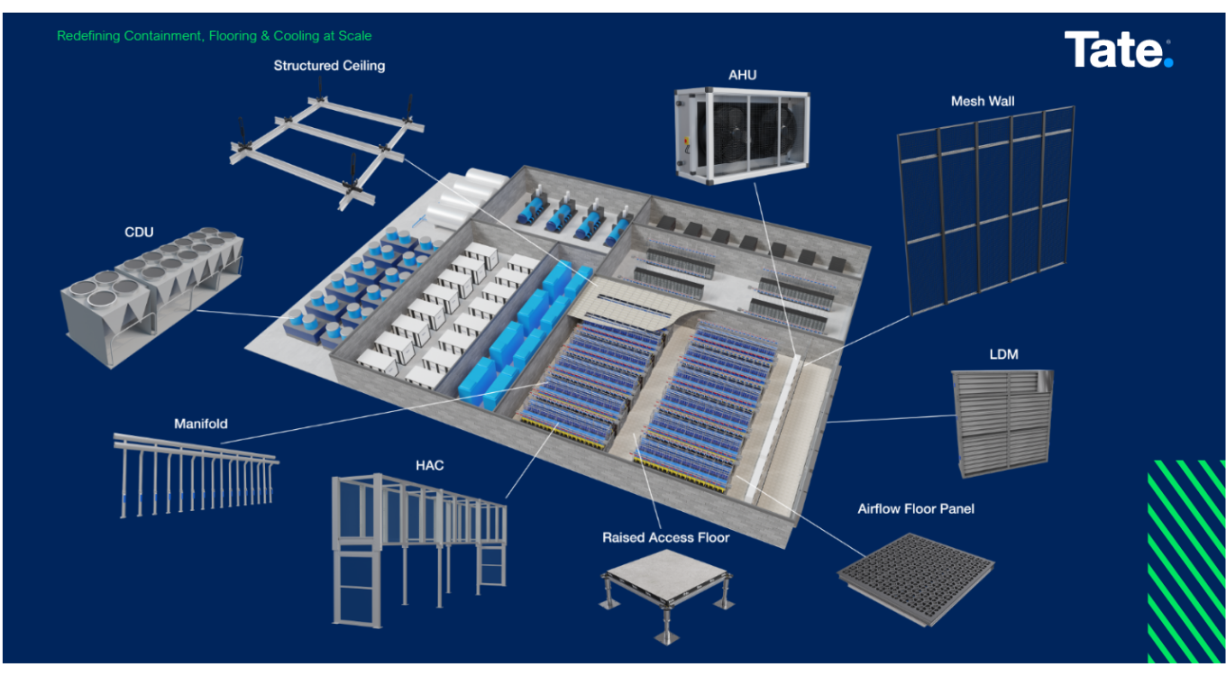
The value of an infrastructure partner becomes clear when the room has to work as a whole. Can the rack get in? Can a technician reach the valve? Can a tenant change cooling systems without rebuilding the hall? Those questions connect the floor, liquid distribution, ceiling, and containment. They should be answered together.
A portfolio that spans the room is needed:
• Raised access flooring: panels, understructure, airflow panels, ramps, steps, fascia, and load-path accessories.
• Liquid distribution: modular manifolds and pipe assemblies for underfloor, in-aisle, and hybrid layouts, with preinstallation or retrofit options.
• Structural ceilings: grid and strut systems that provide organized attachment planes for selected overhead services.
• Air management: containment, doors, mesh partitions, and airflow products that manage the residual air load around liquidcooled IT.
• Integration and execution: coordination, fabrication, inspection, testing, packaging, and support for repeatable programs across sites.
The details meet in real space. A pipe can fit the hydraulic model and hit a pedestal. A rack can satisfy the static-load check and exceed the move-route limit. A containment frame can work thermally and collide with busway or sprinklers. Catch those conflicts on the drawing, and the trades can solve them before installation.
What Raised Access Flooring Adds to an AI Room
In a conventional room, the raised floor may have been discussed mostly as an air plenum. In an AI room, it can serve four roles at once:
1. Transfer rack and equipment loads through a selected panel and understructure system.
2. Create an accessible service zone for coolant, airflow, leak detection, sensing, drainage, inspection, and maintenance.
3. Deliver controlled residual airflow where the thermal architecture requires it.
4. Support future rack moves and layout changes with replaceable, inspectable components.
Those roles have to work together. Higher-capacity panels still need the right pedestals and stringers. Manifold routes need room for leak detection and maintenance. Airflow panels need a controlled return path.
Room for Liquid Distribution
Modular liquid distribution can be placed below the floor, within the aisle, or in a hybrid arrangement. A dedicated underfloor cooling layer can align branches with rack positions, preserve access to valves and connections, and remain visibly separate from overhead power and data. In retrofit work, that can add capability with less disruption to live infrastructure.
The design still begins with operating conditions: fluid chemistry, temperatures, pressure, flow, pipe material, joint method, isolation, redundancy, leak detection, drainage, maintenance clearances, and approved test standard. The manifold is part of a system that extends from heat rejection and primary loops through the CDU and secondary network to the rack.
Structural Ceilings, Containment, and Residual Air
Structural ceiling grid and strut systems can organize overhead attachments while containment defines the air boundary.
Together, they can reduce field-built variability, make future moves more repeatable, and coordinate attachment points with rack rows, liquid drops, doors, and service zones.
The ceiling remains an engineered structure. Project-specific loads, building connections, bracing, sprinkler relationships, and code requirements govern. Use current project submittals to confirm capacities and connections.
Containment deserves the same rigor. Select and commission it for the actual air load, pressure relationships, door operation, fire strategy, and failure modes. The air that remains needs a predictable path in normal operation and under fault conditions.
The Liquid Path is a Load Path
Show each filled manifold, valve group, pipe run, support, and CDU at its actual location in the coordinated model. A CDU may serve many racks, but its weight still lands at its own supports.

Final Thoughts: Design for Change Without Guessing
AI has made physics impossible to ignore.
We can talk about tokens, models, and acceleration all day. Gravity has not read the product roadmap. A 3,200-to-3,500-pound NVL72 rack still has to cross a threshold. An 8,000-pound accelerated computing cabinet needs a verified support system. A liquid-cooled rack may still need substantial airflow. The CDU needs floor space, the coolant adds weight, and the next generation of equipment will need a way into the room.
For owners planning adaptable, high-density halls, raised access flooring deserves serious consideration at the start. It can combine verified load support with an accessible cooling and service layer. Some heavy, stable equipment may belong on slab; an existing facility may call for a hybrid. Choose around the operating model, water strategy, and expected equipment changes, with the loads verified for the actual project.
Bring raised access flooring into that conversation while the room is still on the drawing board, whether the project is a targeted retrofit or a new AI hall. Connect floor capacity and the rack delivery route with underfloor liquid, residual air, overhead power and data, and containment. Carry those decisions through fabrication, testing, installation, and the next refresh. The goal is a data center that keeps working as the compute inside it changes. That is an investment worth getting right.

Read the Full Whitepaper
Written by Bill Kleyman - Contributing Editor of Data Center Programs at Informa and CEO/Co-Founder of Apolo